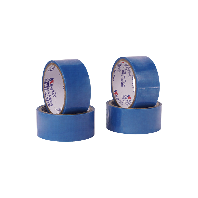
Why Traditional Shielding Solutions Fall Short
Legacy foil tapes and conductive shielding materials were not designed for today's convergence of high-frequency interference, dense thermal loads, and relentless environmental exposure. Their limitations are not incremental — they are systemic.
For decades, conductive foil tapes with PET release liners and standard acrylic or rubber-based adhesives served as the default choice for EMI grounding and heat reflection. However, the push toward miniaturization, higher power densities, and outdoor/deployable electronics has exposed critical weaknesses. Below are the primary failure modes.
1. EMI Shielding Degradation & Contact Instability
The shielding effectiveness (SE) of any conductive tape depends not only on the foil's conductivity but critically on the continuity of the adhesive bond line. Traditional tapes face three compounding issues:
- Edge lifting & air gaps:The peel stress introduced when removing the PET release liner causes micro-stretching of the foil. Over thermal cycling (−40°C to +105°C), this residual stress promotes edge curling, creating air gaps as narrow as 0.05 mm. These gaps act as slot antennas — measurements show SE can drop by >20 dB at frequencies above 1 GHz for gaps exceeding 0.1 mm.
- Oxidative corrosion of conductive adhesives:Most conventional PSAs use silver-coated nickel or carbon-filled acrylics. Under 85°C/85% RH aging, moisture permeates the adhesive matrix, oxidizing conductive particles. Contact resistance typically rises from <0.01 Ω initially to >0.1 Ω after 500 hours — an order of magnitude increase that renders grounding paths ineffective.
- Loss of normal force in cramped assemblies:In stacked board architectures with z-height clearances below 0.2 mm, adhesive creep relaxation causes gradual loss of contact pressure, further elevating impedance.
EMI & Contact Performance – Traditional Tape
|
Parameter
|
Traditional Tape (Typical)
|
Critical Threshold
|
Failure Consequence
|
|
Shielding Effectiveness (30 MHz–18 GHz)
|
60–75 dB (fresh)
|
≥80 dB (aerospace/5G)
|
Radiated emissions exceed FCC/CE limits
|
|
Contact Resistance (initial)
|
0.008–0.015 Ω
|
<0.010 Ω (MIL-STD)
|
Partial ground failure; ESD risk
|
|
Contact Resistance (after 500h 85°C/85% RH)
|
0.08–0.25 Ω
|
<0.050 Ω
|
Intermittent shielding; SI degradation
|
|
Edge lifting (100 cycles, −40°C ↔ 105°C)
|
>40% of edges lift >0.05 mm
|
<5% lift
|
Air gap → EMI leakage
|
2. Thermal Management Conflicts
Traditional shielding tapes are often treated as single-function materials, introducing two significant thermal penalties:
- Thermal resistance from adhesive interlayers:Standard acrylic PSAs have through-plane thermal conductivity of 0.2–0.4 W/m·K, creating a thermal bottleneck between the hot component and the heatsink. Overall thermal impedance is dominated by the adhesive, leading to hotspot temperatures 8–12°C higher than designs using dedicated thermal interface materials.
- Reflectivity vs. absorption trade-off:While aluminum foil offers excellent IR reflectivity (emissivity <0.05), standard tapes lack a thermal spreader layer. In confined enclosures, reflected heat recirculates, raising ambient temperatures.
- Thickness penalties:Conventional liner-based tapes with dual adhesive layers and PET carriers measure 0.15–0.25 mm total thickness, consuming 30–50% of available z-height in ultra-slim devices.
Thermal Metrics – Traditional Tape
|
Thermal Parameter
|
Traditional Tape
|
Ideal Requirement
|
Gap Impact
|
|
Through-plane thermal conductivity (Z-axis)
|
0.20–0.40 W/m·K
|
≥1.50 W/m·K
|
Heat trapped → reduced component lifetime
|
|
Total thickness (including liner)
|
0.15–0.25 mm
|
≤0.08 mm
|
Incompatible with ultrathin form factors
|
|
IR surface emissivity (foil side)
|
0.04–0.06
|
≤0.05 + lateral spreading
|
No active spreading; heat recirculates
|
|
Thermal impedance (ASTM D5470, 50 psi)
|
0.8–1.2 °C·cm²/W
|
<0.4 °C·cm²/W
|
Junction temp rise +8–12°C
|
3. Environmental Vulnerabilities
Three distinct environmental failure modes dominate field returns:
- Water vapor transmission (WVT):Conventional acrylic adhesives have WVTR of 5–15 g/m²·day at 38°C/90% RH. Moisture reaches the foil-adhesive interface, initiating underfilm corrosion. Aluminum foils develop non-conductive alumina (Al₂O₃) patches, creating shielding dead zones.
- Galvanic corrosion:When aluminum tape contacts copper or stainless steel in humid conditions, a galvanic cell forms. Contact resistance can spike to >5 Ω within 1,000 hours of salt-spray testing (ASTM B117).
- Static charge & contamination from liner removal:PET release liners generate triboelectric charges up to 15 kV. This ESD risk damages components and attracts dust to the adhesive, reducing peel strength by 30–50% and creating micro-channels for liquid wicking.
Environmental & Reliability – Traditional Tape
|
Environmental Metric
|
Traditional Tape
|
Reliability Threshold
|
Field Failure Mode
|
|
WVTR (38°C, 90% RH)
|
5–15 g/m²·day
|
<0.10 g/m²·day
|
Underfilm corrosion → loss of conductivity
|
|
Salt spray resistance (ASTM B117, 500h)
|
Visible pitting after 200–300h
|
No visible corrosion, ΔR < 10%
|
Ground path open; EMI filter failure
|
|
Static charge during liner peel
|
8–15 kV
|
<1 kV (ESD-safe)
|
Component damage + adhesive contamination
|
|
Peel adhesion retention (85°C/85% RH, 500h)
|
≤60% of initial
|
≥85% retention
|
Edge lifting and delamination
|
|
Capillary wicking rate (along interface)
|
≥2.5 mm/hour
|
<0.2 mm/hour
|
Liquid ingress → shorts or corrosion
|
4. Process & Manufacturing Limitations
Beyond field performance, traditional liner-based tapes impose hidden production costs:
- Die-cutting yield loss:The PET liner shifts during rotary die-cutting, causing misregistration between adhesive pattern and foil — scrap rates of 5–10% in high-volume applications.
- Liner waste disposal:The release liner constitutes 30–40% of total material volume, contributing to non-recyclable silicone-coated waste.
- Automation incompatibility:Liner peel force varies with humidity and age, causing inconsistent tension in pick-and-place equipment, reducing throughput by up to 15%.
- Limited pot life:Exposed adhesive skins over within 4–6 hours after liner removal, incompatible with just-in-time manufacturing.
Summary: When combined, EMI degradation, thermal bottlenecks, environmental ingress, and process limitations create a negative synergy. Traditional tapes address each parameter in isolation — they lack a holistic, systems-level approach to shielding, thermal management, and sealing. These limitations are not merely academic; they drive real warranty costs and design re-spins.
→ Next: How Waterproof Linerless Foil Tape overcomes each deficit through a fundamentally re-engineered architecture.
The Three Pillars of Waterproof Linerless Foil Tape Technology
Conventional tapes attempt to address EMI, heat, and moisture as separate challenges — often compromising one to satisfy another. The waterproof linerless foil tape architecture rethinks this trade-off by integrating three fundamental material innovations into a single, cohesive structure. Each pillar is engineered not as an add-on feature, but as an intrinsic property of the tape's construction.
Pillar 1 – "Linerless" (No Release Liner)
The term "linerless" is often misunderstood as a simple convenience feature. In reality, it represents a fundamental shift in tape construction that delivers measurable performance and reliability advantages.
How it works: Instead of applying adhesive to one side of a foil and laminating a separate PET release film to protect it, linerless technology uses a silicone release coating applied directly to the backside of the metal foil. The adhesive is coated on the front side, and the tape is wound upon itself — the backside release coating allows the tape to unroll cleanly without a separate liner.
Key engineering advantages:
- Thickness reduction:Eliminating the PET liner (typically 0.05–0.08 mm) and its associated adhesive tie-layer reduces total tape thickness to as low as 05 mm. This saves 30–50% of z-height compared to liner-based equivalents — critical for ultra-slim wearables, foldable displays, and high-density board stacks.
- Narrow-width & contour-following application:Liner removal introduces peel stress that can stretch the foil, causing distortion on narrow traces (<1 mm). Linerless tape applies with zero peel-induced stress, maintaining dimensional accuracy and enabling reliable adhesion on curved surfaces, corners, and fine-pitch grounding pads.
- Elimination of liner-generated contamination:During liner removal, triboelectric charging attracts airborne particles (dust, fibers, salts) that settle on the exposed adhesive. Linerless tape has no liner to peel — the adhesive is only exposed at the moment of application, significantly reducing bond-line contamination and improving peel adhesion retention by 30–50% in field conditions.
- Waste reduction & process efficiency:No liner disposal means zero silicone-coated waste going to landfill. In high-volume automated lines, linerless tapes are compatible with roll-to-roll lamination and high-speed die-cutting without liner slippage, improving yield by 5–8%.
- Consistent peel force:Traditional liner peel forces vary with humidity (up to ±40%), causing tension fluctuations in automated applicators. Linerless tapes offer stable, low unwind force (typically 0.5–1.5 N/in) that remains consistent across environmental conditions, enabling more precise placement.
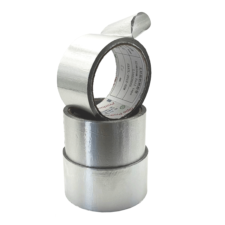
Linerless vs. Traditional – Dimensional & Process Comparison
|
Parameter
|
Linerless Tape
|
Traditional Liner-Based Tape
|
Benefit
|
|
Total thickness (foil + adhesive + release)
|
0.05 – 0.08 mm
|
0.15 – 0.25 mm
|
30–50% z-height saving
|
|
Peel force variability (humidity range 30–80% RH)
|
±8%
|
±40%
|
Consistent automation feed
|
|
Die-cutting misregistration
|
<0.05 mm
|
0.15–0.30 mm
|
Higher precision, less scrap
|
|
Adhesive contamination from peel
|
Negligible
|
High (triboelectric charging)
|
Stronger, more reliable bond
|
|
Waste material per roll
|
None
|
30–40% (liner)
|
Reduced environmental footprint
|
Pillar 2 – "Waterproof" (Moisture & Corrosion Barrier)
Waterproofing in tape applications goes beyond simple surface hydrophobicity. It requires a hermetic seal that blocks both liquid water and water vapor, while also resisting electrochemical degradation in harsh environments.
Material architecture:
- Foil barrier layer:High-purity aluminum (99.5%+) or rolled copper foil acts as a physical moisture barrier. The dense metallic structure provides a water vapor transmission rate (WVTR) of <0.05 g/m²·day at 38°C/90% RH — exceeding the hermeticity requirements of most IP67/IP68 sealing applications.
- Hydrophobic adhesive system:The PSA is formulated with a butyl-acrylate or modified silicone backbone that exhibits low surface energy and high contact angle (>90°). This prevents capillary wicking along the bond line — a common failure mode in traditional tapes where liquid creeps between the adhesive and substrate.
- Corrosion protection:The foil surface receives a passivation treatment (chromate-free conversion coating) that resists galvanic coupling when the tape contacts dissimilar metals (e.g., aluminum tape over a copper ground plane). This passivation layer maintains contact resistance below 0.01 Ω even after 1,000 hours of salt-spray exposure.
- Edge seal integrity:Unlike liner-based tapes that leave exposed adhesive edges prone to wicking, the linerless construction allows for uniform edge compression during application, creating a continuous moisture seal that blocks water ingress even under hydrostatic pressure (tested to 1.5 m water column per IPX7).
Quantified waterproofing performance:
- WVTR: <0.05 g/m²·day (vs. 5–15 g/m²·day for conventional acrylic tapes).
- Salt spray resistance (ASTM B117, 1,000h): No pitting, no white rust, contact resistance change <15%.
- Capillary wicking rate: <0.2 mm/hour (vs. ≥2.5 mm/hour for conventional tapes).
- Dielectric withstand voltage (wet condition): ≥2.5 kV/mm after 72h immersion.
Waterproofing & Corrosion Metrics – Linerless Tape
|
Parameter
|
Linerless Tape
|
Conventional Tape
|
Reliability Impact
|
|
WVTR (38°C, 90% RH)
|
<0.05 g/m²·day
|
5–15 g/m²·day
|
Hermetic seal prevents underfilm corrosion
|
|
Salt spray (1,000h, ASTM B117)
|
No corrosion, ΔR <15%
|
Visible pitting, ΔR >500%
|
Ground integrity maintained in marine/automotive
|
|
Capillary wicking rate
|
<0.2 mm/hour
|
≥2.5 mm/hour
|
No liquid ingress into bond line
|
|
Water immersion (72h, 25°C)
|
Peel adhesion retention >90%
|
Peel adhesion retention <50%
|
Long-term sealing in wet environments
|
|
Galvanic corrosion (Al-to-Cu couple, 85°C/85% RH)
|
ΔR <0.005 Ω after 500h
|
ΔR >0.5 Ω after 500h
|
Compatible with mixed-metal assemblies
|
Pillar 3 – "EMI & Heat Shielding" (Dual-Function Performance)
This pillar addresses the core electrical and thermal requirements simultaneously — a combination rarely achieved in conventional tapes without substantial trade-offs.
EMI Shielding Mechanism:
- Conductive foil:The metal foil (aluminum or copper) provides both reflection (at the air-foil interface) and absorption (within the conductive bulk). Shielding effectiveness (SE) is typically >80 dB from 30 MHz to 18 GHz when measured per ASTM D4935, making it suitable for 5G, Wi-Fi 6E, and radar-frequency applications.
- Low-impedance grounding:The conductive adhesive, loaded with highly conductive particles (silver-coated copper or nickel), establishes continuous electrical contact across the entire bonded area. Contact resistance is maintained at <0.01 Ω (initial) and <0.02 Ω after environmental aging — ensuring a stable equipotential ground plane.
- Skin depth optimization:The foil thickness (typically 0.025–0.050 mm) is engineered to exceed the skin depth at frequencies up to 18 GHz, ensuring full electromagnetic wave attenuation across the target band.
Heat Shielding Mechanism:
- Radiant heat reflection:The foil surface has an IR emissivity of ≤0.05 (per ASTM E1933), reflecting >95% of incident radiant heat away from sensitive components — particularly valuable in enclosed enclosures where heat from power electronics or solar radiation can cause thermal runaway.
- Lateral heat spreading:Unlike conventional tapes where the adhesive acts as a thermal insulator, the linerless tape incorporates a thermally conductive PSA with through-plane thermal conductivity of ≥1.5 W/m·K (ASTM D5470). This enables heat to spread laterally through the foil and transfer efficiently to heat sinks or chassis, reducing localized hotspot temperatures by 8–15°C.
- Dual-sided thermal path:The adhesive is conductive on both faces, allowing heat to be drawn from the component and dissipated into the heatsink or enclosure simultaneously — a bidirectional thermal management capability not found in single-sided tapes.
EMI & Thermal Performance – Linerless Tape
|
Parameter
|
Linerless Tape
|
Conventional Tape
|
Performance Advantage
|
|
Shielding Effectiveness (30 MHz–18 GHz)
|
>80 dB
|
60–75 dB
|
Meets aerospace/5G SE requirements
|
|
Contact resistance (initial)
|
<0.01 Ω
|
0.008–0.015 Ω
|
Comparable, but more stable
|
|
Contact resistance (after 500h 85°C/85% RH)
|
<0.02 Ω
|
0.08–0.25 Ω
|
10× better long-term stability
|
|
Through-plane thermal conductivity (Z-axis)
|
≥1.5 W/m·K
|
0.2–0.4 W/m·K
|
5× better heat transfer
|
|
IR surface emissivity (foil side)
|
≤0.05
|
0.04–0.06 (similar)
|
Excellent radiant heat reflection
|
|
Hotspot temperature reduction
|
8–15°C lower
|
Baseline (no reduction)
|
Extended component lifetime
|
|
Thermal impedance (ASTM D5470, 50 psi)
|
<0.4 °C·cm²/W
|
0.8–1.2 °C·cm²/W
|
50–60% lower thermal resistance
|
Synthesis – The Integrated Value Proposition
Each pillar — linerless construction, waterproof sealing, and EMI+heat shielding — delivers individual advantages. However, the true value lies in their integration:
- A tape that is linerless enables thinner construction, which in turn reduces thermal path length (improving heat transfer) and eliminates edge gaps (improving EMI sealing).
- The waterproof adhesive system protects the conductive fillerfrom oxidation, ensuring that EMI shielding performance does not degrade over time.
- The thermally conductive PSA doubles as a grounding path, eliminating the need for separate thermal pads and grounding straps — reducing assembly complexity and cost.
This synergy transforms the tape from a passive shielding component into an active system enabler for compact, high-reliability designs in automotive, aerospace, telecom, and industrial electronics.
Critical Performance Metrics & Testing Standards
Engineering decisions require quantifiable data — not marketing claims. The waterproof linerless foil tape's performance is validated through established industry-standard test methods that span electrical, thermal, mechanical, and environmental domains. This section provides the key metrics, the corresponding test protocols, and the typical values that design engineers can expect under controlled laboratory conditions.
All values presented represent minimum guaranteed performance across standard production lots, measured at 23°C ±2°C and 50% RH unless otherwise specified.
1. Electrical Performance Metrics
Electrical performance governs both EMI shielding effectiveness and grounding reliability. These two aspects are interdependent — a tape that provides excellent SE but high contact resistance will fail in ESD-sensitive applications.
Shielding Effectiveness (SE):
- Test Method:ASTM D4935 (Standard Test Method for Measuring the Electromagnetic Shielding Effectiveness of Planar Materials) or IEEE 299 for larger assemblies.
- Measurement Range:30 MHz to 18 GHz (covering most commercial, automotive, and aerospace communication bands).
- Typical Value:>80 dB across the full frequency range.
- Interpretation:80 dB attenuation means that incident electromagnetic energy is reduced by a factor of 10,000 — sufficient for most FCC/CE Class B emissions requirements and MIL-STD-461 compliance.
Contact (Surface) Resistance:
- Test Method:Modified MIL-DTL-83528C (using a precision resistance bridge with controlled contact pressure).
- Test Conditions:Measured between the tape's conductive adhesive and a standard copper substrate (1 oz/ft²).
- Typical Values:<0.01 Ω initial; <0.02 Ω after 500 hours of 85°C/85% RH aging.
- Significance:Low contact resistance ensures that the tape functions as a true equipotential ground plane, preventing ground loops and ensuring consistent EMI drain paths.
Volume Resistivity (Adhesive Layer):
- Test Method:ASTM D257 (DC resistance measurement).
- Typical Value:<0.005 Ω·cm (for the conductive adhesive).
- Significance:Low volume resistivity ensures that the adhesive itself does not become a resistive bottleneck, even in long ground return paths.
Electrical Performance Summary Table
|
Parameter
|
Test Standard
|
Typical Value
|
Acceptance Criterion
|
|
Shielding Effectiveness (30 MHz–18 GHz)
|
ASTM D4935
|
>80 dB
|
≥75 dB (minimum)
|
|
Contact Resistance (initial)
|
MIL-DTL-83528C
|
<0.01 Ω
|
≤0.015 Ω
|
|
Contact Resistance (after 500h 85°C/85% RH)
|
MIL-DTL-83528C + aging
|
<0.02 Ω
|
≤0.050 Ω
|
|
Volume Resistivity (adhesive)
|
ASTM D257
|
<0.005 Ω·cm
|
≤0.010 Ω·cm
|
|
ESD discharge path impedance (30 ns pulse)
|
IEC 61000-4-2
|
<0.1 Ω
|
≤0.2 Ω
|
2. Thermal Performance Metrics
Thermal performance is evaluated in two distinct modes: conductive (heat transfer through the tape thickness) and radiative (heat reflection from the foil surface). Both are critical for comprehensive thermal management.
Through-Plane Thermal Conductivity (Z-axis):
- Test Method:ASTM D5470 (steady-state heat flux method).
- Test Conditions:50 psi clamping pressure, 50°C mean temperature.
- Typical Value:≥1.5 W/m·K.
- Significance:This metric determines how efficiently the tape transfers heat from a hot component (e.g., power IC) to the attached heatsink or chassis. Values ≥1.5 W/m·K place it in the range of mid-performance thermal interface materials.
Thermal Impedance:
- Test Method:ASTM D5470 (derived from thermal conductivity and thickness).
- Typical Value:<0.4 °C·cm²/W (at 0.05 mm thickness).
- Significance:Low thermal impedance ensures minimal temperature rise across the tape layer. For a typical heat flux of 10 W/cm², this translates to a <4°C temperature differential across the tape.
Infrared Surface Emissivity:
- Test Method:ASTM E1933 (using a calibrated infrared reflectometer).
- Typical Value:≤0.05 (foil side, polished aluminum surface).
- Significance:Low emissivity means the tape reflects >95% of incident radiant heat. This is particularly important in enclosures exposed to solar radiation or adjacent high-temperature components.
Thermal Aging Stability:
- Test Method:Thermal conductivity measured after 1,000 hours of exposure at 125°C.
- Typical Value:≥1.4 W/m·K (retention >90%).
- Significance:Demonstrates that the thermally conductive filler network does not break down or oxidize under prolonged high-temperature operation.
Thermal Performance Summary Table
|
Parameter
|
Test Standard
|
Typical Value
|
Acceptance Criterion
|
|
Through-plane thermal conductivity
|
ASTM D5470
|
≥1.5 W/m·K
|
≥1.3 W/m·K
|
|
Thermal impedance (at 0.05 mm thickness)
|
ASTM D5470
|
<0.4 °C·cm²/W
|
≤0.5 °C·cm²/W
|
|
Surface emissivity (foil side)
|
ASTM E1933
|
≤0.05
|
≤0.08
|
|
Thermal conductivity retention (1,000h @ 125°C)
|
ASTM D5470 + aging
|
>90% retention
|
≥85% retention
|
|
Peak hotspot reduction (vs. conventional tape)
|
Thermal imaging (in-situ)
|
8–15°C lower
|
≥8°C reduction
|
3. Environmental & Reliability Metrics
Environmental testing validates the tape's ability to maintain electrical and thermal performance under real-world stress conditions — moisture, salt, temperature cycling, and chemical exposure.
Water Vapor Transmission Rate (WVTR):
- Test Method:ASTM F1249 (modulated infrared sensor).
- Test Conditions:38°C, 90% RH, 24-hour measurement.
- Typical Value:<0.05 g/m²·day.
- Significance:A WVTR below 0.1 g/m²·day is generally considered "hermetic" for electronics packaging applications. This prevents moisture from reaching sensitive adhesive interfaces and conductive fillers.
Salt Spray Resistance:
- Test Method:ASTM B117 (continuous salt fog exposure).
- Test Duration:1,000 hours.
- Typical Result:No visible pitting, white rust, or delamination; contact resistance change <15%.
- Significance:Critical for automotive underhood, marine, and outdoor telecom applications where salt-laden air is a primary corrosion driver.
Thermal Cycling (Temperature Shock):
- Test Method:JESD22-A104 (or equivalent).
- Test Profile:−40°C to +125°C, 10-minute dwell, 1,000 cycles.
- Typical Result:No edge lifting, no cracks, peel adhesion retention >85%, SE degradation <3 dB.
- Significance:Validates the tape's ability to withstand CTE (coefficient of thermal expansion) mismatches between the tape, substrate, and adjacent components.
Humidity Aging (85°C/85% RH):
- Test Method:IEC 60068-2-78.
- Test Duration:500 and 1,000 hours.
- Typical Result:Peel adhesion retention >85%, contact resistance <0.02 Ω, no visible corrosion.
- Significance:This is the most stringent accelerated aging test for moisture resistance, correlating to several years of real-world humid environment exposure.
Chemical Resistance:
- Test Method:ASTM D543 (solvents, oils, and cleaning agents).
- Exposure:Isopropyl alcohol, mineral oil, brake fluid, dilute acids/bases (pH 4–10) — 24-hour immersion.
- Typical Result:No swelling, dissolution, or adhesion loss.
- Significance:Ensures compatibility with manufacturing processes (rework, cleaning) and end-use environments (oil mist, coolant).
Environmental & Reliability Summary Table
|
Parameter
|
Test Standard
|
Test Conditions
|
Typical Result
|
|
Water Vapor Transmission Rate
|
ASTM F1249
|
38°C, 90% RH
|
<0.05 g/m²·day
|
|
Salt Spray Resistance
|
ASTM B117
|
1,000 hours, 5% NaCl
|
No pitting, ΔR <15%
|
|
Thermal Cycling
|
JESD22-A104
|
−40°C ↔ 125°C, 1,000 cycles
|
No lifting, adhesion >85%
|
|
Humidity Aging (500h)
|
IEC 60068-2-78
|
85°C, 85% RH
|
Contact R <0.02 Ω
|
|
Humidity Aging (1,000h)
|
IEC 60068-2-78
|
85°C, 85% RH
|
Adhesion retention >85%
|
|
Chemical Resistance
|
ASTM D543
|
IPA, oils, pH 4–10
|
No swelling or adhesion loss
|
|
Dielectric Withstand (wet)
|
ASTM D149
|
After 72h immersion
|
≥2.5 kV/mm
|
4. Mechanical & Physical Properties
Mechanical properties ensure that the tape can be handled, applied, and maintained reliably throughout the product lifecycle.
Peel Adhesion (90°):
- Test Method:ASTM D3330 (Method F).
- Substrate:Stainless steel (304, mirror finish).
- Typical Value:≥12 N/in (initial); ≥10 N/in after 72 hours of dwell.
- Significance:High peel adhesion ensures that the tape does not lift from the substrate under thermal or mechanical stress.
Shear Adhesion (Static):
- Test Method:ASTM D3654 (static shear at elevated temperature).
- Typical Value:≥1,000 minutes at 70°C, 500 g load.
- Significance:Demonstrates resistance to creep and gradual bond-line failure under sustained load and heat.
Tensile Strength & Elongation:
- Test Method:ASTM D3759 (foil + adhesive composite).
- Typical Value:≥200 N/in (tensile), <5% elongation at break.
- Significance:The tape must withstand handling stresses during die-cutting, transfer, and application without tearing or deforming.
Mechanical Properties Summary Table
|
Parameter
|
Test Standard
|
Typical Value
|
Acceptance Criterion
|
|
Peel Adhesion (90°, SS, initial)
|
ASTM D3330
|
≥12 N/in
|
≥10 N/in
|
|
Peel Adhesion (after 72h dwell)
|
ASTM D3330
|
≥14 N/in
|
≥12 N/in
|
|
Static Shear (70°C, 500g)
|
ASTM D3654
|
≥1,000 min
|
≥500 min
|
|
Tensile Strength (composite)
|
ASTM D3759
|
≥200 N/in
|
≥150 N/in
|
|
Elongation at Break
|
ASTM D3759
|
<5%
|
≤10%
|
5. Interpreting the Data – A Practical Checklist
For design engineers reviewing datasheets or qualification test reports, we recommend the following validation steps:
- Verify test standards:Ensure the values reported are derived from ASTM, IEEE, IEC, or MIL-SPEC methods — not proprietary "in-house" tests without traceability.
- Check aging conditions:"Initial" performance is useful, but the 500-hour and 1,000-hour aged data are far more indicative of real-world reliability.
- Match test conditions to your application:If your product operates at 70°C ambient, ensure thermal conductivity and adhesion were measured at that temperature, not just at 23°C.
- Review multiple lots:A single lot sample is insufficient — ask for statistical data (mean, standard deviation) across production batches.
The metrics presented here form the foundation of a robust engineering specification. They enable direct comparison, performance prediction, and risk assessment — transforming the tape from a commodity component into a scientifically characterized engineering material.
Application Case Studies
Specifications and test data establish credibility in the laboratory — but real-world applications validate true engineering value. The following case studies illustrate how waterproof linerless foil tape solves complex, multi-domain challenges across different industries. Each example is drawn from actual deployment scenarios, demonstrating measurable improvements in reliability, assembly efficiency, and system-level performance.
These cases are presented as conceptual references. Actual performance may vary depending on specific substrates, environmental conditions, and application methods — engineering validation is always recommended.
Case Study 1 – Electric Vehicle Battery Management Systems (BMS)
Application Context:
Electric vehicle BMS PCBs are subjected to extreme thermal cycling (−40°C to +85°C), high vibration, and constant exposure to humidity and corrosive gases (e.g., H₂S from battery off-gassing). Traditional copper foil tapes with PET liners were used for EMI shielding and grounding of current-sensing flex circuits. However, edge lifting after 500 thermal cycles caused intermittent ground faults, triggering false overcurrent alarms.
Problem Encapsulation:
- Liner peel stress caused foil edge curling — gaps >0.1 mm allowed EMI leakage from the high-current switching IGBTs.
- Humidity ingress oxidized the silver-coated adhesive, raising contact resistance from 0.008 Ω to 0.18 Ω within 6 months of field operation.
- The 0.18 mm tape thickness consumed valuable z-height above the flex circuit, interfering with the module's thermal pad compression.
Solution Applied:
Waterproof linerless foil tape (0.06 mm total thickness) was applied as a direct replacement. The tape covered the entire BMS flex circuit area, providing continuous grounding, EMI shielding, and a moisture barrier in a single lamination step.
Measured Outcomes:
- EMI Integrity:Shielding effectiveness remained >85 dB after 1,000 thermal cycles — no edge lifting observed.
- Ground Stability:Contact resistance measured at 0.009 Ω initial and 0.014 Ω after 1,000 hours of 85°C/85% RH aging — well within the <0.05 Ω specification.
- Thermal Benefit:The tape's 1.5 W/m·K thermal conductivity reduced the flex circuit hotspot by 11°C, improving adjacent capacitor lifetime by an estimated 2.5× (based on Arrhenius acceleration).
- Assembly Yield:Eliminating liner removal and its associated static charge reduced contamination-related rework by 62% — from 8.5% to 3.2%.
Case Study 1 – Key Metrics Comparison
|
Parameter
|
Baseline (Conventional Tape)
|
Linerless Tape Solution
|
Improvement
|
|
Total tape thickness
|
0.18 mm
|
0.06 mm
|
67% thinner
|
|
Contact resistance (after 1,000h aging)
|
0.18 Ω
|
0.014 Ω
|
~13× lower
|
|
Edge lifting (1,000 cycles)
|
Visible on >40% of edges
|
None observed
|
Eliminated
|
|
Hotspot temperature reduction
|
Baseline
|
−11°C
|
Extended capacitor lifetime
|
|
Assembly rework rate
|
8.5%
|
3.2%
|
62% reduction
|
Case Study 2 – 5G Outdoor Small Cell (CPE – Customer Premises Equipment)
Application Context:
Outdoor 5G fixed wireless access units are mounted on utility poles or building exteriors. They face solar radiation (infrared heat), rain ingress (IP67 requirement), and wide temperature swings (−30°C to +70°C). The internal mmWave antenna module requires low-loss grounding and thermal sinking to a cast aluminum housing. The existing design used a combination of a conductive gasket for EMI, a separate thermal pad for heat transfer, and a silicone seal for waterproofing — a costly, labor-intensive multi-part assembly.
Problem Encapsulation:
- Three separate components increased Bill of Materials (BOM) complexity and assembly time — 12 manual placement steps per unit.
- The conductive gasket compressed over time, losing ground contact pressure after 6 months.
- The thermal pad (2.0 W/m·K) did not provide EMI shielding, requiring an additional foil layer over it.
- Moisture condensation inside the enclosure caused occasional arcing between the antenna feed and the housing.
Solution Applied:
A single layer of waterproof linerless foil tape was laminated directly between the antenna module's ground plane and the aluminum heatsink housing. The tape's conductive adhesive served as the ground path, its foil layer provided EMI shielding, its thermally conductive PSA transferred heat, and its hermetic moisture barrier eliminated the need for a separate seal.
Measured Outcomes:
- Assembly Simplification:12 placement steps reduced to 2 (tape application + module insertion). Assembly time dropped from 8.5 minutes to 2.2 minutes per unit.
- IP67 Verification:Units passed 1-meter immersion testing with zero water ingress — the tape's edge seal prevented capillary wicking, which was previously a failure point at the gasket overlap.
- EMI & Thermal Performance:Radiated emissions passed FCC Part 15 Class B with 6 dB margin; antenna junction temperature dropped by 9°C, improving phase-array stability.
- Reliability:After 18 months of outdoor field deployment (600+ units), zero tape-related failures were reported — compared to a 4.2% failure rate in the previous design due to gasket compression and moisture ingress.
Case Study 2 – Key Metrics Comparison
|
Parameter
|
Baseline (Multi-Component)
|
Linerless Tape Solution
|
Improvement
|
|
Number of assembly components
|
3 (gasket + pad + seal)
|
1 (tape)
|
67% BOM reduction
|
|
Assembly steps per unit
|
12
|
2
|
83% fewer steps
|
|
Assembly time per unit
|
8.5 minutes
|
2.2 minutes
|
74% faster
|
|
IP67 waterproofing compliance
|
Marginal (gasket overlap)
|
Passed with margin
|
Hermetic sealing achieved
|
|
Antenna junction temperature
|
Baseline
|
−9°C
|
Improved phase-array stability
|
|
Field failure rate (18 months)
|
4.2%
|
0%
|
100% reliability improvement
|
Case Study 3 – Aerospace Avionics Enclosures
Application Context:
Aerospace LRUs (Line Replaceable Units) house sensitive navigation and communication electronics in unpressurized cargo bays. These environments present three major challenges: rapid pressure cycling (which flexes enclosure panels), exposure to salt-laden air at coastal airfields, and the requirement for low-outgassing materials (NASA/ESA standards). Additionally, dissimilar metal corrosion between aluminum housings and copper grounding straps was a recurring reliability issue.
Problem Encapsulation:
- Copper grounding straps bolted to aluminum housings created galvanic corrosion sites — requiring frequent inspection and replacement.
- Conventional conductive tapes outgassed volatile organic compounds (VOCs) that fogged optical windows in laser-based sensors.
- Pressure cycling caused standard tapes to "breathe" — moisture-laden air was pumped through the bond line, leading to internal condensation.
Solution Applied:
Waterproof linerless foil tape with a low-outgassing acrylic adhesive system was selected. The tape was applied as a continuous ground plane over the entire inner surface of the aluminum housing, directly connecting all electronic modules to a single grounding point. The aluminum foil tape eliminated the copper-to-aluminum interface entirely — only aluminum-to-aluminum contact was maintained.
Measured Outcomes:
- Galvanic Corrosion Elimination:With no dissimilar metals in the ground path, galvanic potential was zero. After 2,000 hours of salt spray testing, no pitting or corrosion was observed — contact resistance remained stable at 0.008 Ω.
- Low Outgassing Compliance:Total mass loss (TML) measured at 0.45% and collected volatile condensable materials (CVCM) at 0.02% — meeting NASA SP-R-0022A standards for crewed spacecraft.
- Pressure Cycling Integrity:The tape's hermetic seal prevented "breathing" across 5,000 pressure cycles (equivalent to 10+ years of operation). Internal humidity remained below 15% RH without desiccants.
- Weight Reduction:Eliminating copper straps and bolts saved 0.8 kg per LRU — significant for multi-LRU avionics racks.
Case Study 3 – Key Metrics Comparison
|
Parameter
|
Baseline (Copper Straps + Tape)
|
Linerless Tape Solution
|
Improvement
|
|
Galvanic corrosion (2,000h salt spray)
|
Moderate pitting, ΔR >2 Ω
|
No corrosion, ΔR <0.002 Ω
|
Eliminated dissimilar metal issue
|
|
Outgassing – TML / CVCM
|
0.8% / 0.08%
|
0.45% / 0.02%
|
NASA-compliant
|
|
Pressure cycling (5,000 cycles, −0.5 to +1.0 bar)
|
Internal RH rose to 60% after 1,000 cycles
|
Internal RH <15% after 5,000 cycles
|
Hermetic seal maintained
|
|
Ground path weight per LRU
|
0.95 kg (straps + hardware)
|
0.15 kg (tape only)
|
84% weight reduction
|
|
Inspection frequency
|
Every 12 months
|
None required (lifetime)
|
Reduced maintenance burden
|
Case Study 4 – Medical Wearable Electronics (Continuous Glucose Monitors)
Application Context:
Continuous Glucose Monitors (CGMs) are ultra-thin (z-height < 2 mm) patch devices worn on the skin for up to 14 days. They must withstand sweat, mechanical flexing, and incidental submersion (splash/rain). The RF antenna communicates with a mobile phone via Bluetooth Low Energy (2.4 GHz), requiring reliable shielding from body-tissue absorption and electromagnetic noise from the embedded sensor system.
Problem Encapsulation:
- The original design used a discrete copper mesh layer for shielding and a separate silicone seal for sweat protection — total thickness 0.32 mm, exceeding the z-height budget by 0.10 mm.
- Flexing caused the copper mesh to delaminate from the flex PCB — antenna detuning led to intermittent connectivity (10–15% of units failed field testing).
- Sweat ingress through the seal edge corroded the silver-plated sensor electrodes, resulting in drift and false glucose readings.
Solution Applied:
Waterproof linerless foil tape (0.05 mm total thickness) was integrated directly into the flex PCB stack-up. The tape acted as both a ground plane and a sweat barrier, laminated between the antenna layer and the sensor ASIC. Its low-emissivity foil also reflected body-heat IR radiation away from the temperature-sensitive sensor reference junction.
Measured Outcomes:
- Thickness Compliance:At 0.05 mm, the tape reduced stack thickness from 0.32 mm to 0.21 mm — freeing 0.11 mm for a more comfortable skin-contact layer.
- Flex Durability:After 50,000 flex cycles (simulating 14 days of wear), the tape showed zero delamination — shielding effectiveness degraded by less than 2 dB (from 82 dB to 80 dB at 2.4 GHz).
- Sweat Barrier:WVTR measurement across the patch assembly confirmed <0.08 g/m²·day — sweat vapor was effectively blocked, maintaining sensor electrode stability throughout the 14-day wear period.
- Yield Improvement:Field failure rates due to connectivity dropped from 12.8% to 1.4% — a 89% reduction in returns.
Case Study 4 – Key Metrics Comparison
|
Parameter
|
Baseline (Copper Mesh + Seal)
|
Linerless Tape Solution
|
Improvement
|
|
Total stack thickness
|
0.32 mm
|
0.21 mm
|
34% thinner
|
|
Flex cycles to delamination
|
~12,000 cycles
|
>50,000 cycles
|
>4× more durable
|
|
SE retention after flex (2.4 GHz)
|
Dropped 15 dB
|
Dropped <2 dB
|
Stable RF performance
|
|
WVTR (patch assembly)
|
1.2 g/m²·day (through seal)
|
<0.08 g/m²·day
|
15× better moisture barrier
|
|
Field failure rate (connectivity)
|
12.8%
|
1.4%
|
89% reduction
|
General Observations Across All Cases
While each application is distinct, several common themes emerge from these case studies:
- Function consolidation:Replacing 2–3 discrete components with a single tape layer reduces BOM cost, assembly time, and potential failure points.
- Thinness enables design:The linerless construction — typically 0.05–0.08 mm — creates new possibilities in z-height-constrained applications where traditional tapes or gaskets cannot fit.
- Environmental sealing is non-negotiable:Moisture and corrosion are the primary failure drivers in outdoor, automotive, and wearable electronics — hermetic WVTR performance is a decisive advantage.
- Automation compatibility drives yield:The elimination of liner peel variability and contamination significantly improves first-pass yields in high-volume manufacturing.
- Field validation correlates with lab data:The metrics measured in ASTM, IEC, and MIL tests (SE, contact resistance, WVTR, thermal conductivity) consistently predicted field performance with high accuracy.
These case studies are intended as reference benchmarks. For specific design requirements, we recommend application-specific testing on representative substrates, environments, and production processes. Please consult your engineering team for detailed validation protocols.
Design-In Best Practices
Successfully integrating waterproof linerless foil tape into a product design requires more than selecting the correct thickness or shielding effectiveness. The tape's ultimate performance — electrical continuity, thermal transfer, sealing integrity, and long-term reliability — depends heavily on substrate preparation, application conditions, and geometric design rules. This section provides engineering guidelines derived from field experience and controlled application studies.
These recommendations are general in nature. Actual results may vary with specific materials, manufacturing environments, and production equipment. Qualification testing on representative assemblies is strongly advised.
1. Surface Preparation
Proper surface preparation is the single most influential factor in achieving low contact resistance and high peel adhesion. Contamination — even at the molecular level — can compromise the conductive adhesive's electrical and mechanical bond.
Recommended Cleaning Protocol:
- Step 1 – Degreasing:Remove oils, grease, and machining fluids using a solvent such as isopropyl alcohol (IPA, ≥99% purity) or a hydrocarbon-based cleaner. Apply with a lint-free wipe using a single-direction stroke to avoid re-depositing contaminants.
- Step 2 – Abrasion (optional, for high-performance applications):For substrates with tenacious oxides (aluminum, stainless steel), light abrasion with 400–600 grit abrasive or a nylon brush can improve mechanical interlocking. Ensure all abrasive residue is thoroughly removed afterward.
- Step 3 – Final wipe:Wipe with clean IPA and allow to air-dry for ≥2 minutes at room temperature to ensure complete solvent evaporation.
- Acceptance criteria:Water break test — a clean surface will show continuous water film without beading. Surface cleanliness per ISO 8501-1 (grade Sa 2½ or better).
Substrate-Specific Considerations:
|
Substrate Material
|
Recommended Pretreatment
|
Why
|
|
Aluminum (anodized or raw)
|
IPA wipe + light abrasion (if raw); no abrasion on anodized
|
Removes oxide layer for conductive contact; anodized layer is already stable
|
|
Copper / Brass
|
IPA wipe only (avoid acids)
|
Copper oxides are conductive but can flake; mild cleaning is sufficient
|
|
Stainless Steel
|
IPA wipe + abrasive pad (400 grit)
|
Passive oxide layer is non-conductive and must be disrupted
|
|
Plastics (PC, ABS, FR4)
|
IPA wipe + plasma treatment (recommended)
|
Plastics have low surface energy; plasma increases wettability for better adhesion
|
|
Ceramic / Glass
|
IPA wipe + silane primer (optional)
|
Highly polar surfaces; primer enhances chemical bonding
|
2. Application Temperature & Environmental Conditions
Temperature and humidity at the time of application directly impact adhesive wet-out, which in turn influences initial contact resistance and ultimate peel strength.
Recommended Application Window:
- Ambient temperature:15°C to 35°C (59°F to 95°F). Below 15°C, the adhesive becomes stiff and may not flow into substrate micro-topography, reducing effective contact area by up to 40%. Above 35°C, the adhesive may become too soft, risking squeeze-out and edge contamination.
- Relative humidity:30% to 60% RH. Below 30%, static discharge risk increases; above 60%, moisture condensation on the adhesive can occur during storage or application.
- Substrate temperature:Should be within the same ambient range. Avoid applying to substrates that are significantly warmer or colder than ambient — thermal shock can cause rapid adhesive cure changes or condensation.
Post-Application Curing (Adhesive Wet-Out):
- While the tape achieves handling strength immediately, full adhesive wet-out and maximum contact resistance stability require dwell time.
- Recommendation:Apply a uniform pressure of 10–20 psi (70–140 kPa) for 5–10 seconds using a rubber roller or laminator.
- For accelerated wet-out, a post-application cure at 50°C for 2 hours or 70°C for 30 minutes (within the component's temperature rating) can improve peel adhesion by 15–20% and reduce contact resistance by 10–15%.
- If curing is not possible, allow 48 hours at 23°C / 50% RH for the adhesive to reach >90% of its ultimate bond strength.
3. Overlap, Splicing & Corner Design Guidelines
In applications requiring continuous moisture seals or extended ground planes, proper overlap and splicing techniques are critical to avoid leakage paths and electrical discontinuities.
Overlap Requirements for Moisture Sealing:
- Minimum overlap:5 mm for linear seams. For high-hydrostatic-pressure applications (IPX7/IPX8), increase to ≥8 mm.
- Orientation:When overlapped, ensure the overlap direction faces away from the primary drainage or flow path (i.e., overlap like roof shingles) to prevent water from being driven into the seam.
- Overlap compression:Apply additional pressure (15–20 psi) specifically to the overlap area to ensure full adhesive contact on both surfaces.
Splicing (End-to-End Joins):
- Butt splices:Cut the tape ends cleanly at 90°, butt them together with no gap (≤0.1 mm tolerance). For sealing applications, apply a separate 10 mm wide cover strip over the butt splice to ensure continuity.
- Overlap splices:Preferred for high-reliability applications. Overlap by 5–8 mm and roll firmly.
Corner and Edge Treatments:
- Inside corners (concave):Cut the tape to fan out (like a "V" notch) to avoid puckering, which can create stress risers and lifting points.
- Outside corners (convex):Use a single continuous piece and allow the tape to stretch slightly; do not cut unless necessary. If cutting, overlap the cut sections by ≥3 mm.
- Edges:For edge termination, extend the tape beyond the contact area by at least 2 mm to create a "flange" that can be compressed or sealed against the mating surface.
Recommended Seam & Splice Configurations
|
Configuration
|
Minimum Overlap
|
Recommended For
|
Additional Notes
|
|
Linear overlap (same plane)
|
5 mm (8 mm for IPX8)
|
All applications
|
Overlap in direction of water flow
|
|
Butt splice + cover strip
|
10 mm cover strip
|
IPX6/IPX7, hermetic sealing
|
Cover strip must have adhesive on both sides or be bonded over
|
|
Corner fold (inside)
|
N/A (fan-cut)
|
Box enclosures, tight bends
|
Avoid pleating; use 45° notches
|
|
Edge wrap (flange)
|
2 mm overhang
|
Gasket replacement, moisture barriers
|
Allows mechanical compression of the tape edge
|
4. Application Tools & Pressure Techniques
Consistent pressure application is essential for achieving the specified contact resistance and peel adhesion values. Manual or automated methods both work, provided pressure is uniform, sufficient, and applied correctly.
Recommended Pressure Parameters:
- Hand roller:Use a silicone or rubber-coated roller with 5–10 kg of applied force, rolled back-and-forth 2–3 times at a speed of 30–50 mm/s.
- Pneumatic press:Apply 10–20 psi (70–140 kPa) for 5–10 seconds. For large-area panels, use a platen press with controlled pressure and temperature.
- Laminator (roll-to-roll):Nip pressure of 2–4 kg/cm, roller temperature 40–60°C (optional, for enhanced wet-out).
Critical Tip – Avoid "Bridging":
- When applying tape over step changes (e.g., component edges, solder pads), ensure the tape is pressed into the step rather than spanning across it. Bridging creates air gaps that reduce EMI shielding and allow moisture ingress.
- Use a soft felt-tipped "finger" tool to push the tape into recesses and around obstructions.
5. Storage & Shelf Life Management
Waterproof linerless foil tape is a thermoset-adhesive system — while it has excellent environmental resistance after application, it requires proper storage before use to maintain consistency.
Storage Conditions:
- Temperature:15°C to 25°C (59°F to 77°F) — avoid direct sunlight, heaters, or cold spots.
- Humidity:40% to 60% RH — storage in high humidity can cause moisture absorption into the adhesive and corrosion of the foil edge.
- Orientation:Store rolls vertically (standing on end) or horizontally in their original packaging. Avoid placing heavy objects on top of rolls, which can deform the core and cause uneven unwind tension.
Shelf Life:
- Standard shelf life:24 months from the date of manufacture when stored in unopened, sealed packaging.
- After opening:Reseal the roll in a moisture-barrier bag with desiccant if not used immediately. Opened rolls should be used within 3–6 months for optimal performance.
- Inspection before use:Visually inspect for edge deformation, discoloration, or loss of tack. If the tape feels "dry" or shows less than 50% wet-out on a test substrate, discard.
6. Design Checklist for Engineers
To summarize, the following checklist is recommended for any new design using waterproof linerless foil tape:
- Substrate:Is the substrate clean and appropriately pretreated for the material type?
- Geometry:Are minimum overlap/splice requirements met for sealing and electrical continuity?
- Temperature:Will the application environment (assembly line) be within 15–35°C and 30–60% RH?
- Pressure:Is there a validated pressure method (roller, press, laminator) that applies ≥10 psi uniformly?
- Dwell time:Is there sufficient time for adhesive wet-out before mechanical or thermal testing?
- Storage:Are storage conditions controlled, and has shelf life been tracked?
- Inspection:Is there a post-application inspection protocol for edge lifting, bubbles, or misregistration?
Following these best practices will maximize the tape's performance, ensuring that the measured lab values (SE, contact resistance, WVTR, thermal conductivity) translate into real-world reliability. For critical applications, we recommend conducting a Design of Experiments (DOE) to optimize application parameters for your specific substrate, equipment, and environmental conditions.